Allstar has a telemetry capability, but the hardware that it uses, called a ‘chameleon’ is nowhere to be found. To satisfy this need, I decided to go about reproducing it. The result of this effort was ‘PUTSI’: a PIC USB Telemetry System Interface. Acronyms within acronyms. Love it!
The first task was to determine how the protocol worked. It uses a serial port on the pi (or host machine) to communicate with the device, which made discovering how it worked relatively simple. After ploughing through the 26,000 lines (ugh!) of the repeater app, and using a terminal program to receive, it became apparent.
The next step was to design and write a simulator in C for a PC, so I could behave like a chameleon and turn on digital outputs, set analog voltages, and monitor digital outputs. With that in hand, I was able to send messages to Allstar and see how it reacted. There is no documentation on how the analog (aka meter-faces) component works, so that will have to be done by guesswork.
Finally, it was time to create some hardware. I had used a PIC microcontroller for another project, and had developed the necessary code for implementing a UAR/T on both windows and Linux. The basic design was enhanced to add a WIFI part for a secondary reporting capability. Both the USB and WIFI modes can be used simultaneously.
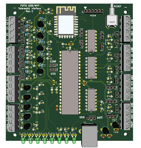
This particular PIC has an 8-channel A/D converter as well as a plethora of digital inputs and outputs. The analog inputs are buffered with an op amp, and I added a capability for additional buffering using jumpers. The digital inputs are buffered with a single transistor which can tolerate up to 12v inputs, and the outputs are buffered with FET’s that can sink up to 60ma, so they can control small relays if necessary.
The firmware is somewhat simplistic; it constantly scans the A/D converters and inputs, and responds to requests from Allstar for updates. Similarly, when a command is received to change an output, it is updated right away. The device is configured by Allstar, but the number of A/D channels, inputs and outputs are fixed.
In the WIFI mode it uses the USRP protocol to send a packet that contains the current analog readings and digital inputs. A response packet is sent back with the requested state of the digital outputs.
The documentation has recently been updated to add two application notes, one for measuring temperature and a second to measure current. The project has been handed over to the Alberta Digital Radio Communications Society for deployment.
View the full manual here: