A software suite has been developed to both configure and monitor analog voltages reported by the controller hardware. Configuration data for each channel provides a scalar and offset to restore and/or convert the data, then apply two sets of limits:
- Range. The minimum and maximum range that will be seen after the conversion has been applied.
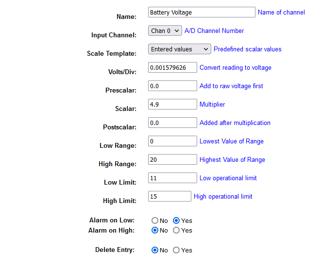
- Limits. Sets the normal operational limits for the channel in the converted units.
The configuration and monitoring software runs on a web-based platform. The figure below shows a sample configuration for the battery voltage. It consists of data to restore the original value, the range and operational limits. Alarms are generated based on high or low thresholds, or both.
The monitoring software runs on the same platform as the configuration, below is a sample from a repeater that used the data show above for one of its channels.

The meter icon on the left side shows the current status of the channel. The colour reflects the current status:
- Green. Monitored data is within its normal operational limits.
- Orange. Outside the normal limits, but no alarm has been generated.
- Red. Alarm condition.
- Red with Stripes. Outside the specified range. No alarm is generated in this state.